Artikel: Hoses and Conduits Rattling in the Locker? 3D Print a 2-Piece Pipe Clamp Sized to the Tube
Hoses and Conduits Rattling in the Locker? 3D Print a 2-Piece Pipe Clamp Sized to the Tube
Open any locker on a boat that has had a few owners and you will find the same thing: a water hose zip-tied to a wiring loom, a conduit hanging off one cable clip that gave up years ago, and a bilge pump line that has worn a shiny groove into the plywood behind it. Every one of those runs moves when the boat moves. Under way they rattle, they chafe, and eventually a hose splits or a cable insulation wears through exactly where nobody can see it. The fix is not complicated, but it depends on one thing chandlery clamps rarely give you: a clamp that is the right size for the tube you actually have. This guide covers a printed two-piece pipe clamp with a built-in stand-off post that you size to the millimetre, and how to use it to make hose and cable runs quiet and permanent.
Why loose runs fail on a boat
On land a hose lying on a shelf lives forever. On a boat the whole shelf accelerates in three axes, thousands of times an hour, for years. Anything not held firm rubs against something, and the harder material always wins: a stainless hose clamp will cut through PVC, a plywood edge will cut through a cable jacket, and a metal conduit vibrating against a fibreglass liner will polish through the gelcoat. The other failure is fatigue at the ends. A hose that flops in the middle works its fittings at each end; the barb that seemed tight at the dock loosens after a season of flexing. Sensible boatbuilders support every run at short intervals so nothing can flex, and they lift it off the surface so water cannot sit between hose and bulkhead.
The trouble is the hardware. Plastic P-clips come in a handful of nominal sizes that never quite match a 19 mm reinforced hose or a 25 mm flexible conduit; too small and you cannot close them, too big and the tube slides through. Stainless saddle clamps are strong but crush soft hose and start galvanic trouble against aluminium. And none of them stand the run off the wall: they press it flat, which is exactly where moisture and chafe live.
A clamp you size instead of choose
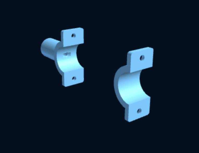
The Pipe Wall Clamp with mounting post is a parametric file: you type in your dimensions, preview the part in 3D, and receive an STL cut to those numbers. It is two half-collars that bolt around the tube with two side screws, the heads countersunk into the outer half so nothing sticks out to catch a hand or a sail bag. On the back of the inner half is a solid cylindrical post with a through-bore for the mounting screw. The bore is countersunk on the inside of the collar, so the screw head sits flush inside the post and never touches the tube. That detail matters: it means you can tighten the clamp hard to the bulkhead and the hose only ever sees smooth plastic.

Everything you would normally have to compromise on is a parameter:
- Tube diameter: the exact outside diameter of your hose, conduit, rail or rod-holder tube.
- Clamp width: wider for soft hose that you want to hold without crushing, narrower for rigid conduit in a tight space.
- Clamp-bolt diameter: match it to the stainless screws you already carry, M4 or M5 for most jobs.
- Post height, from 5 to 100 mm: this is the stand-off. A short post lifts a run just clear of the surface; a tall one carries a hose over a stringer, a wiring bundle or a layer of insulation without a spacer block.
- Post bore diameter: the mounting screw. The file keeps the bore at least 3 mm smaller than the post so there is always a safe wall of plastic around it.
Because the collar is round and closed, it will also hold a tube it was never designed for in a chandlery: a fishing rod holder along a cockpit coaming, a 20 mm alloy rail for a modular storage kit, or a fibreglass whip antenna base.
Measuring before you configure
Take the tube diameter with callipers, not a tape, in two places at right angles, and use the larger number. Reinforced hose is often slightly oval and slightly bigger than its nominal bore plus wall; a 19 mm hose is frequently 27 mm outside. If you are clamping soft hose, add half a millimetre so the collar closes firmly without pinching the wall; for rigid conduit or metal tube, use the measured figure and let the print's own tolerance provide the grip. For the post height, measure from the mounting surface to the point where you want the centre of the tube to sit, then subtract half the tube diameter and the collar wall. Where the run crosses a stringer, make the posts on either side tall enough that the hose passes over it in a gentle curve, not a kink. If you have never dialled a printer in for close fits, our tolerance calibration guide takes twenty minutes and pays for itself on the first clamp.

Material and print settings
The product page recommends PETG or ASA, and the choice is simple. Inside the boat, in lockers, under bunks and along the engine-room bulkhead, PETG is the right default: it shrugs off damp, does not creep under a modest clamp load, and prints on any machine. Anywhere the clamp will see sun, whether a cockpit rail, a deck conduit or the lazarette under a clear hatch, use ASA for its UV stability; PETG goes brittle after a couple of seasons outdoors. If you are supporting something heavy or lively, such as a rod holder or a long unsupported rail, the file is also listed for CF-PETG and CF-Nylon, which are much stiffer but need a hardened nozzle. Our materials guide goes into the trade-offs.
The recommended settings are 0.2 mm layers, 3 perimeters and no supports; the part is designed to print flat. Put the flat mating face of each half on the bed, which keeps the countersinks clean and orients the layers so the clamp screws pull across layers rather than trying to split them. Bump infill to 40 per cent or more for the post, since that is the column carrying the load. A single clamp is a fifteen to forty minute print depending on size, so a full locker's worth is an evening.
Installation
Space the clamps closer than you think: roughly every 300 to 400 mm for hose, 500 mm for rigid conduit, and always one within 100 mm of any fitting so the hose cannot lever on the barb. Mark the post positions with the tube in place, drill, and mount the inner half first with a stainless pan-head screw through the post. Into plywood a self-tapper is fine; into thin fibreglass liner, use a machine screw and a nut or a rivnut behind, and if you would rather not drill the boat at all, read our drill-free mounting guide for the adhesive options. Lay the tube in, drop on the outer half and drive the two side screws until the collar just closes; you are locating the hose, not compressing it. With the countersinks on the outer half, the finished run is flush and snag-free.

Related parts
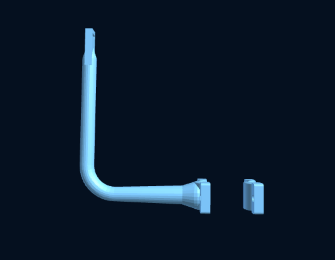
If you are routing cables rather than hose, or want to hang gear from a rail instead of fixing the rail itself, three sibling designs in the same family are worth a look. The Tube-Mount Clip Holder is the same two-piece collar with a clip receiver instead of a post, for hanging torches, tools and bottles from an existing tube. The Custom Wall Clip Holder is the flat-mount version for bulkheads. And the free Twin Pipe-Clamp Cross Bar turns two clamps on a rail into a bar you can hang the modular jar and holder kits from. For the bigger picture on keeping runs tidy, see our guides to boat wiring cable management and bilge hose guides, or browse the whole plumbing and pumps collection.
Safety note
3D-printed parts are not certified marine equipment. A printed clamp is a support, not a structural fitting: it should locate hose and cable, not take the loads of standing rigging, steering, gas or fuel lines, or anything whose failure would sink or burn the boat. Check that the material suits the temperature and chemicals it will see, keep printed parts out of the raw-water system below the waterline unless you have tested them for it, and inspect every print before it goes in. If you are unsure whether a run is a good candidate, email info@marinelab3d.com with a photo and the tube size and we will tell you honestly.